Is the RMS Error of a DF System as Important as Some Manufacturers Would Have You Believe?
Some of our competitors go to extraordinary lengths to talk up the significance of 1° RMS error and to get it specified in tenders as the supposed gold standard. Ever wondered why? It’s because they can limit the competition and can charge a hefty premium. As they say, “no one ever got fired for buying IBM”.
But is 1° RMS error a meaningful number and is it worth paying for? As I explain below, when it comes to using DF systems in the real world, the 1° RMS error claim is not really worth the paper it is written on. How so?
First you need to understand what the 1° RMS error claim means and how it is calculated. RMS error is the sum of tolerances of the various elements of the system – for example, in the measurement of amplitude or phase of the signal, variation over temperature range, quantization of analog signals to digital, etc. In principle, these tolerances can be measured and minimised through calibration to very low levels depending on your test set up. In order to get down to levels as low as 1° RMS error, some manufacturers have invested in very complex test and calibration systems carried out in the ideal conditions of an Open Air Test Site (OATS) or anechoic chamber. They have pushed to the limit the law of diminishing returns to squeeze out every last degree of RMS error. The existing ITU recommendationsi suit these manufacturers well and they have used their presence on ITU committees to try and maintain the status quo.
CRFS has taken a different view. We are not interested in “over-specing” our systems. We care about providing our customers with the best value for money DF systems designed to work reliably in the messy real world rather than worrying about hitting a 1° RMS error in an anechoic chamber! Our systems are specified at typical 3 to 5° RMS error across the frequency range, which in the real-world environment is good enough. Indeed, in real-world side by side trials by one of our customers, our systems significantly outperformed the so-called “1° guys” when it came to finding rogue transmitters fast and reliably.
Ask the Right Question
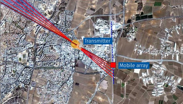
What is the main difference between the 1° RMS error ideal conditions of the test chamber and the real-world environment? In the test chamber, signals travel in a predictable manner from transmitter to receiver without encountering obstacles. In the real world, signals are subject to objects such as hills, trees and buildings. With buildings for example, signals start bouncing off walls creating multiple copies of signals arriving at the DF system from multiple directions. This is called multipath. The 1° RMS error of the test chamber becomes irrelevant in a multipath environment where the system could be pointing in completely the wrong direction. Much more important than the absolute RMS error are the features of the system for counteracting multipath effects and that is where CRFS has concentrated its efforts.

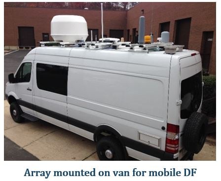
Our Research and Development team in Cambridge has put a lot of work into DF algorithms to manage the effects of multipath as far as possible, with signal processing used to average results and eliminate outlying readings affected by multipath. Our Cumulative Tracking software feature is also really useful for this. It uses a vehicle mounted RFeye Array to generate multiple bearings from different positions to build up a geolocation and to reduce multipath effects.
Fortunately, the ITU is recognising the need for RMS error measurements which are relevant to the real world and several recommendations are currently being drafted for measurement of on-site DF accuracy of fixed and mobile systems.
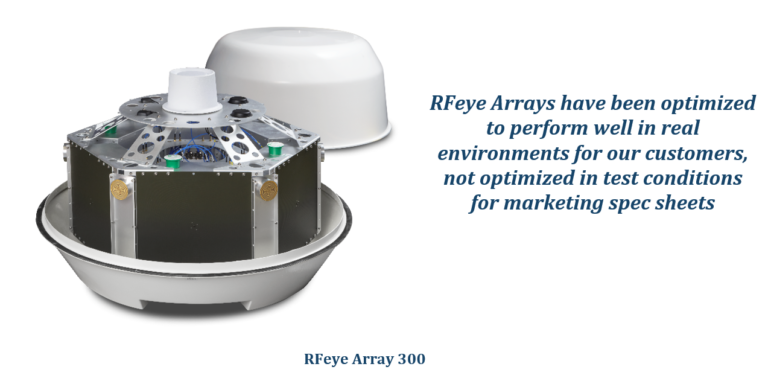
But even real-world RMS error isn’t the whole story anyway. CRFS has focused on other elements of its DF systems that have a significant impact on real-world performance well beyond the impact of RMS error. For example, we use close coupling of receivers and antennas to minimise cable losses and improve sensitivity rather than the typical long cable runs of our competitors’ systems; we use spiral antennas for detecting any linear polarisation rather than the typical antennas of our competitors that can detect only horizontal or vertical polarisations.
So don’t get so hung up on an RMS error number. Look at the bigger picture.
Contact us for more information. We are very transparent about our data, we can simulate the performance of our systems for your environment or arrange a live demo.
Want to know more? Check out our RFeye Arrays and our Cumulative Tracking feature.
The ITU has several publications which provide guidance and recommendations on testing DF RMS error, including:
- Spectrum Monitoring Handbook
- ITU-R SM.2125-1 Parameters of and measurement procedures on H/V/UHF monitoring receivers and stations
- Rec. ITU-R SM.2097 On-site accuracy measurements of a fixed DF system
- ITU-R SM.2060 Test procedure for measuring direction finder accuracy
The typical test procedure takes measurements at a range of azimuths and frequencies, filling in a table such as this:
From these results, an average is calculated to give the “Typical RMS error” seen on datasheets.

Brochures, Guides & Survey's
RFeye Array Overview
Ultra wide frequency, high performance radio direction finding up to 40 GHz.


