Direction Finding (DF) equipment is an incredibly costly investment, so you want to make sure you get it right, and that it suits your exact testing requirements. A lot of ideas sparking CRFS innovation are conceived by the feedback and the experience of many of our clients, many in the regulatory and MOD space, frustrated with their inability to make the most of their large investments with this technology, and reproduce the expected results and data in the field.
Once you’ve invested into your DF system, the time to ask is over – so the time to ask is before you buy and make sure you quiz and talk to your vendor very deeply about accuracy and signals of interest. Let’s have a look at some of the common mistakes that are made, and discuss some of the design criteria and usability guidelines, in order to optimize your product.

Direction Finding (DF) Accuracy
Your AOA processing engine is typically designed to compute and provide a single line of bearing which is then very handily superimposed on a map. Mathematically this will be the weighted average bearing of all the incoming energy at a certain frequency range, and effectively you should consider it as the line of bearing along which the energy arrives at the antenna array.
It’s one of the key misconceptions utilizing data from any DF system – the Angle of Arrival (AOA) processing engine will blindly compute and produce this line of bearing with the data it receives regardless of whether this data is good or bad quality and hence whether the output is good or bad quality. Ultimately the system is reporting which bearing the energy is arriving at the DF system in, in multipath or strong reflection conditions this may be a very different bearing to the true bearing of the source. This pencil thin line reaching out into infinity represents a mathematical output, blindly following this line of bearing is simply where the madness lies and many clients reluctantly admit spending hours and days fruitlessly following the error.
One of the key questions I would encourage you to be asking is where is your DF in terms of its accuracy and its repeatability? How does it handle all the parametric variation it encounters? How does it crunch its data and what can you do to ensure you maximize the value of the intelligence you’re extracting from your system?
Invest in Your Training
While DF equipment is incredibly useful, many clients are utilizing these tools without a deep knowledge of the limitations in real-life situations, and how to best interpret the data they obtain in order to make informed decisions. It is not only money that needs to be invested into these devices, you also need to invest appropriate time and effort on training. Training to understand the way the devices work, how to correctly set up them up, the impacts of environments, and importantly, the correct interpretation of the data. Training can be extremely time-consuming and can also use up very valuable resources, so again one of those key questions you should be posing to your vendor is how does your DF system and the software suite allow me to accomplish this and really maximize my resources?


Topography – The Forms and Features of Your Land Surface
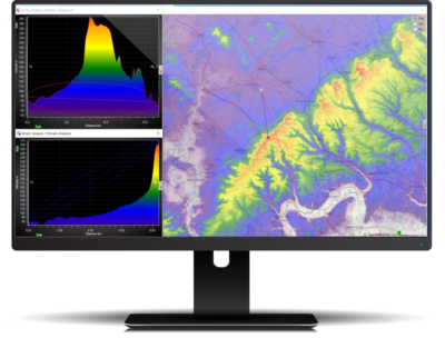
An often overlooked point is the impact of topography, this is a critical element to understand the consequences on the measurements you’re making and the quality of those measurements. The classic response to ground bounce, reflections and other topographic influences is to raise the antenna, the DF system, up to height whether it’s on a tower or a pneumatic mast. However it’s important to note that you’re not completely removing the impact of ground bounce, plus you’re also adding many other practical problems. For instance, there have been installations where the receiver and antennas are separated by tens of meters of Radio Frequency (RF) cable. When you consider that at 1GHz every meter of RF cable adds around 3dBs of additional loss, it’s also acting as an antenna and collecting noise. The net impact is that the cable can completely desensitize your receiver. This effects the dynamic range of your device and the ability to detect signals beyond certain power level. There is also a commercial impact – how much DF equipment are you going to need to cover the required geographic area of interest?
Thinking Outside the Box with Vehicle Installations
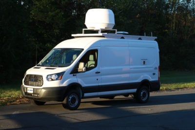
There are key strategies you can employ to mitigate the impact of ground bounce, reflection and topographic effects. One of the best practical scenarios that we advocate, is using the DF equipment on a mobile platform. This helps break the multipath conditions that maybe experienced, and successfully geolocate signals even in tough environments.
For further reading on direction finding vehicles tackling the urban obstacle course, please read “Direction Finding (DF) in Urban Environments”.

Choosing the Correct Radio Frequency Product
Another critical design choice in a DF system are the choice of antenna. The exploitation of the RF spectrum is tremendous, the range of different signals of interest that you encounter and are looking to DF against is enormous; analog to digital, narrow to wide band, Continuous Wave (CW) to extremely high modulation rates, sweeping signals, hopping signals, signals inside of signals, I could go for hours. The paths you face are complex and extremely challenging, so need a solution to match up to the task.
Systems are extremely sensitive to the input signal polarization, they also have different operating ranges and this drives the need for different antenna sets for different frequency ranges and for different input polarization. Although this represents a hidden cost, it does offer technical advantages that many clients simply don’t see until after they receive the systems and start putting them into practice.
CRFS Solution
CRFS uniquely advocate the use of hybrid geolocation technology, we’ve even designed our kit specifically to facilitate that. The smart strategy would be to add AOA and TDOA missions together- the hybrid geolocation approach from the same instrument. Many different DF instruments won’t allow you to do this, so as a result of feedback, the CRFS DF systems are specifically designed to be multitaskers, performing AOA missions but be able to still engage in sweeping capture and TDOA missions as well.
Conclusion
With the RF environment becoming increasingly saturated, it is vital to maintain situational awareness. Never be afraid to challenge your vendor and ask questions. Collaboration and testing will ensure you stay ahead of the game, and fulfill your objectives . By taking into account these factors, you will be able to extract the most value from your DF equipment.
Watch the Webinar
We have released the AoA Accuracy – Myths and Legends webinar exclusively on demand. Watch it here!

Brochures, Guides & Survey's
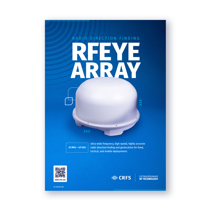
RFeye Array Overview
Ultra wide frequency, high performance radio direction finding up to 40 GHz.
