6 factors affecting minimum detectable RF signal and maximum detection range when detecting signals of interest

You may want to understand better the radio frequency (RF) signal profile of your assets, equipment, and people. You might want to improve connectivity across a long distance marked by obstacles. Or perhaps you want to protect your installation from unauthorized devices more precisely. Whatever the situation, knowing the factors that can influence the strength and range of signals is vital.
Although every RF signal-related solution is unique to its purpose and environment, several factors influence the minimum detectable signal for a given range and, conversely, the maximum range for a given signal power.
In this article, we will review six main mission-dependent factors that can influence RF signal range. We’ll also explore how simulation tools can help organizations better estimate and predict minimum detectable signal and maximum detection range.
Six factors that influence the detection of an RF signal
In most cases, six factors can impact the strength and range of an RF signal:
- Interfering signals
- Obstacle effects
- Friis transmission loss
- Cable loss
- Noise floor
- Processing gain
We will focus on a minimum detectable signal use case to better define how each of these factors can affect an RF signal. Because minimum detectable signal and maximum detection range are closely related problems, many of the same principles will apply.
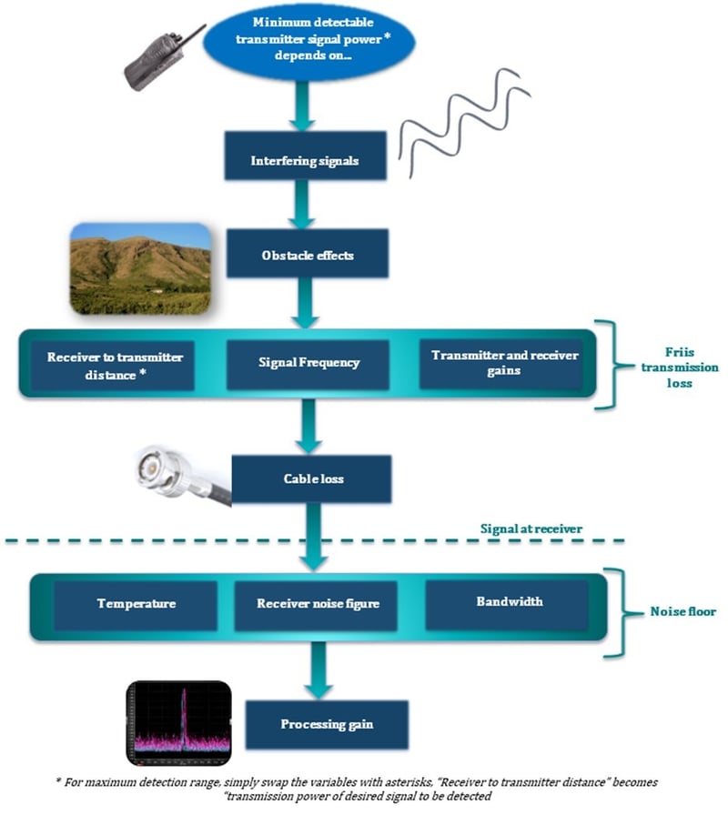
The following scenario follows an RF signal transmitted from a radio handset through the six influencing factors to the target receiver to determine the minimal signal that can be detected:

1. Interfering signals
Other signals present in the frequency band of interest can impact the strength of the target RF signal. Depending on the extent of interference and the presence of other factors, RF signal detection may still be possible using signal processing techniques.
2. Obstacle effects
Many minimum detectable RF signal principles assume the free space is ideal, meaning there are no obstacles in the way.
However, in real-world scenarios, this is rarely the case. Therefore, one has to factor in physical obstacles, such as buildings, trees, and mountains, that can block, diffract, and reflect signals. This causes them to be subject to multipath effects or lost entirely. When monitoring large areas, the earth’s curvature can also introduce an obstacle effect on signal propagation.
Placing a receiver at a higher point, such as the top of a building, mountain, or pole, can help minimize the signal-diminishing effects of obstacles.
3. Friis transmission loss
Friis transmission loss involves several factors working in concert to affect signal power between the transmitter and the receiver:
- Distance
- Frequency
- Antenna gains
According to the Friis transmission equation, RF signal power decreases by the square of the distance from the transmitter antenna to the receiver antenna. This means the distance an RF signal travels between antennas is doubled, and the power is reduced by a factor of four.
RF signal power also decreases with the square of frequency. In practice, this means that a higher-frequency signal reduces the effective aperture of both the receiver and transmitter antennas.
One way to mitigate these effects is to use a directional antenna, which may help increase received signal power.
4. Cable loss
As an RF signal continues its path, cable loss can impact its ultimate power or range. The cabling used between the antenna and the processing unit can introduce some signal attenuation, primarily due to skin-effect and dielectric losses.
How much the signal is affected depends on cable parameters such as the cable’s length and material and the signal frequency. RF signal losses increase with increases in cable length and signal frequency.
5. Noise floor
Continuing through the scenario, the processing unit's ability to detect and distinguish a given signal power from other captured noise will also affect the RF signal. The lower the noise floor of the receiving device, the easier a signal will be to detect.
In most cases, the additional noise is primarily thermal, which increases as temperatures rise due to increased agitation of charge carriers. Since thermal noise is approximately white (constant power with frequency), it will also increase with bandwidth. In this case, bandwidth corresponds to receiver fast Fourier transform bin width.
The receiver noise figure, indicating the extent of noise amplification by the receiver, can also affect the noise floor. To help operators isolate signal from noise, a device’s noise figure is usually stated on receiver datasheets.
6. Processing gain
The type of signal processing technique in use is the final factor affecting how easily an RF signal can be detected and its strength type of signal processing technique in use. For example, operators can detect RF signals below the noise floor using the output from two receivers to correlate the RF signals.
How simulation tools improve target RF signal detection and range estimates
Simulation solutions, including software solutions help defense organizations, government agencies, and communications regulators create more accurate projections of RF signal detection ranges and strengths. Using real-time spectrum monitoring, geolocation technology, and propagation analysis tools, operators can mitigate signal interference and degradation that impact minimum detectable signal and maximum detection range estimations.
With the right tool, users can go beyond a generic minimum detectable signal value to determine a more accurate, mission-specific minimum detectable signal or maximum detection range using values that closely represent real-world conditions.
Simulation tools can be used to model different types and strengths of interference signals, including:
- Broadcast digital TV
- Mobile phone
- Private mobile radio/digital mobile radio
- Illegal transmitters
This capability has practical applications for use cases such as border monitoring, when operators need to provide coverage along the length of a physical or geographical border.
Some simulation tools can also model various placements and heights of receivers to determine what level of frequency signals can be detected. For example, if someone has a mobile phone in a given location, the simulation will show whether a particular configuration of receivers will detect it given the various factors that can diminish or obscure the signal. Changing the signal type and receiver placement can help the operator optimize the configuration for maximum signal detection.
Additionally, propagation modeling tools allow operators to overcome obstacle effects by simulating signal propagation that takes full account of topographical and terrain obstacles, human-made obstacles and even the earth’s curvature. Using this data, operators can optimize receiver positioning virtually before installing and deploying hardware in the real world.
Conclusion
The ability to accurately determine the strength of an RF signal or properly account for the distance that it has to travel can be the difference between operational success or failure.
Consequently, it’s important to understand how these six factors can influence an RF signal and why using an industry-leading simulation platform is worth the investment.
