Traditional direction-finding systems provide a single line of bearing to a target, as shown below in Figure 1. RFeye Site, on the other hand, can provide far more detail, and does so with a user-friendly interface, allowing operators to extract the maximum amount of geolocation information from incoming signals.
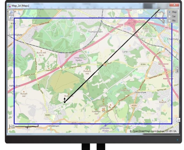
Figure 1 Single Line of Bearing (LOB)
Feature 1 – Color-Coded Lines of Bearing
RFeye Nodes have multi-user, multi-mission capability, which means each Node can be simultaneously generating lines of bearing to numerous signals. To keep track of what’s going on at a glance, the line of bearing can be color-coded according to which Node is generating it (as in Figure 2) or according to which signal it is locating (as in Figure 3).
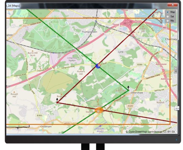
Figure 2 LOBs color-coded according to Node
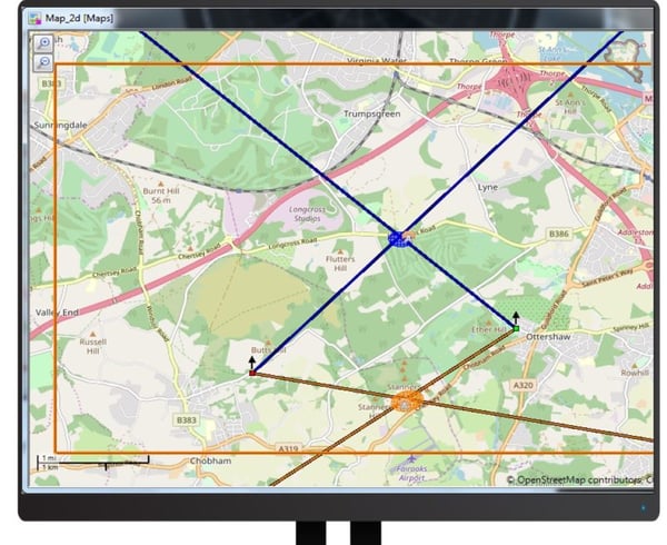
Figure 3 LOBs color-coded according to signal
LOBs can also be color-coded according to their quality, based on signal-to-noise ratio, LOB variation and signal spread associated with multi-path or co-channel interference. Green LOBs (for example) indicate high-quality bearings, amber medium quality and red low quality, allowing the user to intuitively understand how reliable each result is.
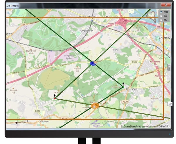
Figure 4 LOBs color-coded by quality
Feature 2 – Replacing Lines with Wedges
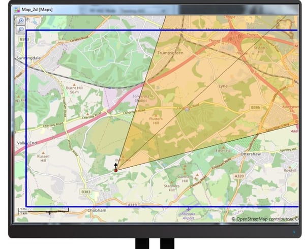
Lines of bearing can give a false sense of accuracy. Building on the quality color-coding shown above, RFeye Site can display the range of angles that the incoming signal could originate from. This view also makes the relationship between signal quality and reliability of the LOB explicit – with high quality, green signals generating a narrow range, while the lower quality amber signal results in a much wider range of possibilities.
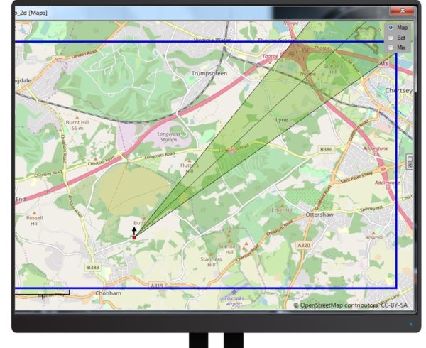
Figure 5 High quality signal generating tight wedge
Want to find out more about direction finding in RFeye Site? Download the “AoA Accuracy Myths and Legends” webinar, or contact us for a demonstration.